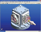
 Figure 1 CAD software for building a 3D solid model |
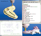
 Figure 2 EdgeCAM software can perform multiple types of programming |
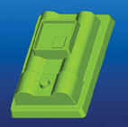
 Figure 3 is compatible with multiple CAD software |
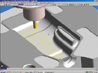
 Figure 4 EdgeCAM provides physical and machine simulation capabilities |
CNC machining has become one of the symbols of manufacturing modernization. Today's CNC machining equipment has many types and different structures. They all need corresponding software platforms for support, so that they can fully exert their efficiency. Therefore, CNC programming system has grown up with it. As we all know, the numerical control programming system is a software environment running on a computer, which can realize offline programming, which not only greatly saves the debugging time of the numerical control machine tool, but also can fully utilize the advantages of the computer to complete the calculation task of large workload and make the writing. The work of the CNC machining program is simple and fast. As such, the development of CNC programming systems is inseparable from the development of computer hardware and software environments.
At the time of the rise of the Windows operating system in 1993, people of insight began to develop a CAM system based on a personal PC running on a Windows platform, because the CAM system required a computer with powerful computing power, but the personal computer hardware performance at that time. There is still a certain gap with the requirements, which has become a bottleneck in the application of CAM systems. Until 1998, some CAM software began to transfer all development and application environments to the Windows platform. Prior to this, most of the CAM software was running on a large computer or workstation, and the CAM software running on a personal PC was basically developed and operated in the Dos environment. Developing CAM software on the Windows platform, it is impossible to upgrade or upgrade the source code on the platforms such as Dos, Unix, etc., and must "start another stove", so not all CAM software developers have the courage and ability to get out of this step. . This is also the reason for the different development environments in current CAM systems.
With the improvement of computer hardware performance, people are not satisfied with the functions of 2D CAD. They are beginning to yearn for and pursue the intuition and convenience of 3D CAD. At first, people built 3D models through wireframes, and then built complex 3D part models and surfaces. Models are also widely used. Although the 3D model is intuitive, the space and computational load on the computer suddenly increased. The 3D solid model became the unbearable weight of the PC at that time. For some time, the 3D CAD software has become the test environment for high-performance personal computers. But what is exciting is that the hardware performance of personal computers has been rapidly improved in a short period of time. Software based on building 3D solid models has also emerged and is quickly accepted by users. A number of representative CAD software based on building 3D solid models have emerged, such as SolidWorks, Solidedge, Inventor and other software. During the booming period of CAD software, the development of CAM software did not stagnate, and many software vendors began to work on the development of software environments for programming solid models. Also as a three-dimensional model, due to the difference in model structure, the CAM software is very different in the process of generating the tool path for the surface model and the solid model. The surface model is constructed by cutting and stitching a plurality of curved sheets to construct a three-dimensional model. The effect of cutting and stitching between the curved sheets is also greatly different according to the software environment. The solid model first builds the model through the solid features, and the second part can also be combined by "Boolean operation", so that the constructed solid part model is a complete independent element. As the basis for tool path calculation in the CAM environment, the integrity and accuracy of the 3D model is critical. If the 3D solid model is transformed into a surface model to process, or the surface elements are extracted from the 3D solid model to calculate the tool path, the information integrity and validity of the solid model relative to the surface model are completely lost. Advantage. However, the calculation of the tool path directly for the solid model requires a great modification of the internal algorithms and application framework of the software. Therefore, in the early development of the CAM software for the surface model, in order to avoid the modification of a large amount of the underlying code, the familiar method of processing the surface model was followed, and the programming operation of the solid model was processed according to the surface model to make people Quickly adapt to the programming of the solid model, without feeling the difference between the solid model and the surface model.
Under this background, Pathtrace took the lead in completing this “transformation†and in 1994 began developing a new product, EdgeCAM, on the Windows platform. It inherits more than a decade of software development experience in the CAM field by Pathtrace, and is designed to directly interoperate with the current widely used 3D solid model, combining bold innovation and accurate judgment of future market trends. Out of a unique CAM software development path.
First of all, in terms of applicability, EdgeCAM software can perform various types of programming such as turning, milling, turning and milling, wire cutting, etc. Different programming types are concentrated in one interface, and users can easily switch between different programming types. . Because the software development environment uses the Windows platform, EdgeCAM becomes a true Windows application, not just the window mode interface. Common shortcuts for Windows are found in EdgeCAM. As a 3D application software, OpenGL is supported, and dynamic operations such as rotational movement of the model can be realized by mouse operation. When most CAM software developers passively turned to the Windows platform, EdgeCAM has been firmly on the road for nearly a decade.
In view of the current trend of machine tools, EdgeCAM has also shown its unique side in the field of high-speed machining and multi-axis machining. In high-speed machining, EdgeCAM offers a variety of machining methods such as cycloidal machining, spline interpolation, spiral contouring, plunge milling, and cavity machining. For high-speed machining, the software provides flexible tool import and export methods that can be processed automatically. The fillet connection changes the cutting direction and automatically adjusts the feed rate; roughing and its residual material processing can possibly reduce the residual height. In multi-axis machining, EdgeCAM supports five-coordinate linkage, providing a variety of five-axis machining methods, supporting five-axis multi-surface machining, five-axis contour machining, five-axis drilling, side cutting machining and five-axis simulation. And in high-speed machining and five-axis machining, EdgeCAM operation is more intelligent and simple, and often only requires a few simple parameters to quickly complete very complex programming.
Secondly, the acceptability of the front-end CAD data and the connectivity of the back-end machine tools are all issues that users need to consider, which is directly related to the user's existing equipment.
In terms of model compatibility, Pathtrace has abandoned its usual practice of loneliness and adopted a horizontal joint approach to jointly design and develop file interface modules through cooperation with CAD software vendors to achieve full compatibility and become A model of industry development. Up to now, Pathway has cooperated with companies such as Autodesk, Dassault, UGS, PTC, etc. to develop data interfaces for 3D CAD solid models such as Inventor, CATIA, SolidWorks, Solidedge, Parasolid, Pro/E, etc., which not only guarantees model data. From the CAD environment to the CAM environment, it can also be linked to these CAD environments. Thoroughly solved the problem of model incompatibility. At the same time, in order to better inherit the thinking habits of the surface model programming, and other CAM environments based on surface model programming, the file interface of intermediate formats such as IGES and VDA is set. In terms of programming operation, the advantages of the solid model are maximized, and the programming operation process is greatly reduced by automatically finding the processing features and automatically setting the processing parameters. The tool path calculation is directly carried out for the whole solid model, which changes the application and development of CAM software due to the overcutting and mistakes caused by the trimming, stitching and mis-selection of the surface model in the previous surface model processing. To a new realm.
Next page
Eye Liner Bottle,Plastic Eyeliner Bottle,Eye Liner Tube
Anda Aluminum Co., Ltd. , http://www.chinacosmeticbeauty.com