1 Introduction
2 MoS 2 “soft†coating research progress at home and abroad
- Matrix selection
- As the support of the coating, the influence of the substrate on the coating properties is self-evident, and sometimes even directly determines the success or failure of the coating process. The substrate and coating should be matched in physical properties and chemical properties. It is necessary to consider whether the matrix has high hardness, whether the parameters such as elastic modulus and thermal expansion coefficient are reasonable and whether there is chemical reaction with the coating.
- Jing Yang et al. compared the microhardness values ​​of MoS 2 composite coatings prepared on ZL108 aluminum alloy (90 ~ 110HV) and relatively hard 1Cr18Ni9Ti (370HV) materials, and found that the hardness of the latter is nearly 1/1 higher than the former. 5 times. The authors analyzed that the high-hardness matrix is ​​not susceptible to plastic deformation and can delay the premature tearing and spalling of the coating due to plastic deformation of the matrix, which is similar to the hard interlayer in the multi-coating and composite coatings. The surface layer is supported; at the same time, the microhardness of the composite coating is also significantly improved.
- The difference in thermal expansion coefficient and elastic modulus between the substrate and the coating or coating and the coating results in a residual stress field of unequal size and uneven distribution between the coating interfaces. After Jing Yang et al. deposited the TiN-MoS 2 /TiN composite coating on the surface of YG8 and YT14, it was found that the residual stress state between the layers was the residual tensile stress of the coating and the residual compressive stress of the matrix. The coefficient of thermal expansion d TiN > d YG8 or d YT14 (see Table 1). Finally, the stress state inside the coating is: the residual compressive stress of the YT14 matrix is ​​reduced, and the YG8 matrix has a larger difference in thermal expansion coefficient compared with the TiN coating, so that not only the compressive stress disappears, but also a certain tensile stress is generated. The stress state has changed before and after. The existence of the residual stress field affects the bonding force between the coating and the substrate, and the greater the difference between the layer-base thermal expansion coefficient, the greater the residual stress, and the lower the bonding force between the layer and the base, which adapts to the wide temperature difference environment. The ability is worse. Therefore, when selecting the substrate, materials with different parameters such as thermal expansion coefficient and elastic modulus and the matrix should be selected as much as possible to reduce the residual stress and improve the bonding force between the coating interfaces.
- The literature also tested MoS 2 /TiN on the surface of Cu and carbon steel, and the coating failed. The authors found that the coating reacted with the matrix during the deposition process. The CuO contained in the impure Cu reacted with the H + which was decomposed into the H 2 S gas flowing into the deposition chamber to form water vapor, which produced the so-called hydrogen. Disease phenomenon:
CuO + 2H + → Cu 2+ + H 2 O - When the water vapor expands, the formed crystal grains are broken, resulting in pits of about 0.5 mm on the surface of the Cu substrate, so that the coating cannot be deposited at all. Similar conclusions have been made on the experimental analysis of carbon steel substrates. Therefore, the chemical properties of the layer-base are also considered when selecting the substrate. It should be noted that the use of materials with similar chemical properties gradually forms a transition layer (gradient coating), which has been widely used in multi-coating and composite coatings: the closer the performance, the more reasonable the material matching performance, between the coating interfaces. The stronger the bonding force, the easier it is to form a transfer film, and the better the wear resistance, the longer the life of the soft coating.
Table 1 Performance parameters of several substrates and coating materials material parameter hardness
(HV)Thermal expansion coefficient
( × 10 -6 mm/mm ° C)coating MoS 2 400 10.7 Base or intermediate layer High speed steel M42 steel ordinary twist drill 860
740±30≈12 Cemented carbide YG8
YT141400
15004.5
6.5ceramics TiN
Si 3 N 42500
16009.4
3.4- Table 1 lists the hardness and thermal expansion coefficient values ​​for MoS 2 and several matrix and intermediate coating materials.
- MoS 2 coating process
- Coating method
- The MoS 2 coating method is divided into a chemical vapor deposition (CVD) method and a physical vapor deposition (PVD) method. Compared with the CVD method, the PVD coating method has a low processing temperature and a compressive stress inside the coating, which is more suitable for the hard and complex tool coating of the cemented carbide, and has no adverse effect on the environment, and is in line with the development direction of modern green manufacturing. MoS 2 "soft" coatings are currently prepared using sputtering techniques, ion plating techniques (or a combination of both) in the PVD process. However, as the current mainstream deposition method for magnetron sputtering MoS 2 coating, the coating quality and deposition rate obtained have been unsatisfactory. Teer et al. developed a deposition method called closed magnetic field unbalanced magnetron sputtering ion plating (CFUBMSIP), which is gradually being applied to the preparation of "soft" coatings. Figure 1 is a schematic view of its structure.
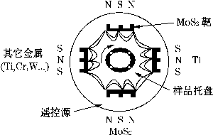
Fig.1 Schematic diagram of closed magnetic field unbalanced magnetron sputtering ion plating system- Increasing the ion current density during magnetron sputtering is the key to improving the performance and efficiency of sputter coatings. The generation of ions is initially based on a balanced magnetron source. The CFUBMSIP system is characterized by the use of an unbalanced magnetron source in the vacuum chamber. The magnetic fields of adjacent magnetrons in the system have opposite polarities, resulting in a toroidal magnetic field throughout the vacuum chamber. After the trapping of the parallel magnetic field on the surface of the cathode target, the secondary electrons cannot directly fly to the anode, but then fall into the trap of the closed magnetic field with an approximate cycloid motion, thereby increasing the collision probability of electrons and gas molecules. The amplitude increases the ionization rate of the gas and the ion current density that can be obtained by the cathode target, allowing the system to have a higher sputtering rate.
- Table 2 shows the performance comparison between the MoST (MoS 2 + metal or compound) composite coating prepared on the surface of M42 steel and the pure MoS 2 coating using this system. It can be seen that the performance of the composite coating is significantly improved.
Table 2 Comparison of performance between MoST composite coating and pure MoS 2 coating parameter Hardness (HV) Coefficient of friction Wear rate
(m 3 /Nm)Pure MoS 2 400 0.08 to 0.15 (RH 50%) 4×10 -5 MoST 1000~2000 0.02 to 0.1 (RH 40%) <4×10 -7 - Han Chengming et al. proposed a non-equilibrium nanocomposite plasma coating method (NCUPP) based on the concept of “multiphase materials†in the development of materials. The principle is to use gas discharge to make gas or be evaporated under specific process parameters. The material is ionized, and ion bombardment is generated while depositing vapor or other reactants on the substrate. In this way, fine nanocomposites can be performed on several to a dozen different materials, so that several layers or even dozens of multi-phase nanocomposites are contained in the coating of 2 to 3 μm thick. The design principle is shown in Figure 2.
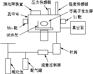
Figure 2 System diagram of unbalanced nanocomposite plasma coating method- Using this method, several materials (Ti, N, Mo, S, etc.) were finely nanocomposited. TiN-MoS 2 /Ti multiphase nanocomposite coatings were prepared on 1Cr18Ni9Ti stainless steel sheets and f 8 twist drills. X-ray photoelectron spectroscopy (XPS) tests show that part of Ti exists in the form of oxides, forming a dense oxide film on the surface of the coating, preventing further oxidation of the coating, thereby improving the moisture resistance of the nanocomposite coating. . The wear comparison test shows that the friction coefficient of nanocomposite coatings hardly changes with the wear life, indicating that the wear life of TiN-MoS 2 /Ti multiphase nanocomposite "soft" coating deposited by NCUPP method is much higher than that. Ordinary TiN-MoS 2 /Ti coating.
- Coating process
- The parameters of the coating process also affect the bonding force of the "soft" coating interface, which in turn affects the overall performance of the coating. These parameters include: Ar gas pressure, cathode current density, substrate negative bias and magnetron sputtering conditions (target distance, metal or compound addition, etc.). Table 3 shows the process parameters of the TiN-MoS 2 /Ti nanocomposite coating prepared by NCUPP method.
Table 3 Process parameters of TiN-MoS 2 /Ti nanocomposite coating Sedimentary layer Vacuum degree
(Pa)atmosphere
(Pa)bias
(V)Target current
(A)Deposition time
(min)temperature
(°C)TiN 2×10 -2 N 2 (0.5) 200 80 30 200 MoS 2 /Ti 2×10 -2 Ar(0.3)
H 2 S (2.5)Mo target Ti target Mo target Ti target 15 200 150 70 90 80 - The literature examined the effects of Ar gas pressure, magnetron power mode, sputtering target type, liquid nitrogen cold trap, etc. on coating properties. The results show that the coating obtained at a lower Ar gas pressure (0.40 Pa in the test) is superior to the coating obtained at a higher pressure (0.88 Pa); the wear volume of the coating prepared by a single DC power source is greater than that of the double Coating under pulsed DC power supply; wear volume of coating prepared under liquid nitrogen cold trap conditions is smaller than coating under liquid nitrogen-free cold trap; cold target preparation under conditions of relative humidity and low Ar gas pressure (0.44 Pa) The coating has a slightly higher wear volume than the hot target, but the opposite is true for coatings at higher Ar gas pressures, as shown in Figure 3.
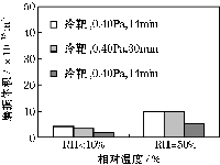
(a) Ar pressure is 0.40Pa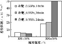
(b) Ar pressure is 0.88PaFigure 3 Wear volume of MoS 2 coating obtained under different Ar pressure, cold or hot targets 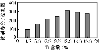
(a) Drilling life of the drill bit at different Ti contents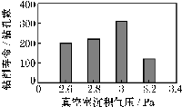
(b) Drilling life of drill bit under different deposition pressuresFig. 4 Effect of different parameters on the drilling life of the drill - Jing Yang et al. conducted drilling tests on the AZ5032 drilling machine under atmospheric conditions, and examined the properties of TiN-MoS 2 /Ti composite coating prepared on the surface of f 8mm 6542 steel twist drill by NCUPP method, and the performance of the coating. The relationship between magnetron sputtering conditions (target distance, deposition pressure, and Ti additive content). The authors found that the drilling life of the coated tool is directly related to the Ti content, but does not increase linearly with increasing Ti content, but reaches the highest when the Ti content is about 12.5% ​​(see Figure 4a, test). The maximum number of holes in the medium is 310). As the target distance decreases and the deposition pressure increases, the Ti content increases. When the target distance is too small (less than 50 cm) and the deposition pressure is too large (more than 3.0 Pa), the Ti content increases significantly, resulting in a coating. The internal lattice is severely distorted, and the distortion can increase rapidly, resulting in a rapid decrease in the wear life of the coating and loss of the desired lubrication (see Figure 4b). After many experiments, the authors concluded that the composite coating obtained with the target distance of 50cm and the deposition pressure of 3.0Pa (the Ti content of about 12.5%) is the best.
- The MoS 2 coating method is divided into a chemical vapor deposition (CVD) method and a physical vapor deposition (PVD) method. Compared with the CVD method, the PVD coating method has a low processing temperature and a compressive stress inside the coating, which is more suitable for the hard and complex tool coating of the cemented carbide, and has no adverse effect on the environment, and is in line with the development direction of modern green manufacturing. MoS 2 "soft" coatings are currently prepared using sputtering techniques, ion plating techniques (or a combination of both) in the PVD process. However, as the current mainstream deposition method for magnetron sputtering MoS 2 coating, the coating quality and deposition rate obtained have been unsatisfactory. Teer et al. developed a deposition method called closed magnetic field unbalanced magnetron sputtering ion plating (CFUBMSIP), which is gradually being applied to the preparation of "soft" coatings. Figure 1 is a schematic view of its structure.
- In addition, the pre-sputter cleaning of the substrate before deposition can remove impurities that are not conducive to the bonding of the coating to the substrate. For the MoST coating, a metal sputtering target (such as a Ti target) can be opened at the same time as the cleaning process, and the vacuum can be reduced. The concentration of indoor water vapor; ion bombardment of the coating by applying a certain negative bias to the substrate during the deposition process can improve the interdiffusion ability of the layer-base component and the atomic reactivity of the coating surface, thereby reducing The generation of defects in the coating. Considering the above factors comprehensively, the literature has the lowest friction coefficient and the best wear resistance under the conditions of ion pressure of 0.40Pa, cathode current density of 10A/cm 2 and simultaneous application of -100V negative bias. MoS 2 coating.
- Jing Yang et al. compared the microhardness values ​​of MoS 2 composite coatings prepared on ZL108 aluminum alloy (90 ~ 110HV) and relatively hard 1Cr18Ni9Ti (370HV) materials, and found that the hardness of the latter is nearly 1/1 higher than the former. 5 times. The authors analyzed that the high-hardness matrix is ​​not susceptible to plastic deformation and can delay the premature tearing and spalling of the coating due to plastic deformation of the matrix, which is similar to the hard interlayer in the multi-coating and composite coatings. The surface layer is supported; at the same time, the microhardness of the composite coating is also significantly improved.
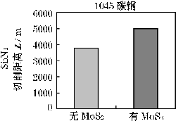
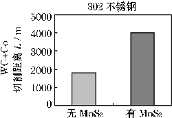
3 Application effect of MoS 2 “soft†coated tool
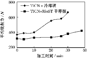
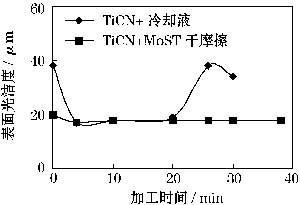
|
|
| Figure 5 Comparison of the effects of two different coated tools | |
|
|
|
|
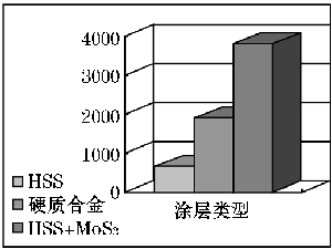
| Figure 8 Comparison of wear life of ceramic tools with/without MoS 2 coating | |
4 Conclusion
Expandable Container House,Buy Shipping Container Home,Expandable Container House With Ensuite,Prefab Expandable House
Suzhou Daxiang Container House Co, Ltd , https://www.dx-house.com
