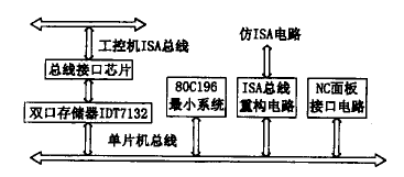
The communication machine plays a role in the system. It receives the various axis position commands from the Pentium 166 interpolation and distributes these instructions to the position control board through the parallel port. In addition, the communication machine also provides management functions for the buttons and indicators of the CNC panel. The design of the communication machine is shown in Figure 2. The imitation ISA bus in the figure provides a channel for transmitting information between the communication unit and the position control board. At this time, the "imitation ISA bus" is designed according to the needs of the position control board and the common control card. It reconstructs part of the signal of the standard ISA bus, including: various signal lines and interrupt signals required for I/O operation. Line, ready control, power line, etc. The position control board designed according to the "Imitation ISA Bus" is fully compatible with the standard ISA bus. There are two advantages to this: 1 In the system development phase, the design and debugging of the communication unit and the position control board can be completed separately by means of the microcomputer, and there is no successive dependency between the two; 2 in a system with a small number of control axes The first structure in Fig. 1 can be used, and the position control board can be directly inserted into the bottom plate of the industrial computer to conveniently realize the reorganization of the system.

Figure 2 Communication machine design principle
During the design process, we used a custom dedicated bus between the communication unit and the position control board. The dedicated bus is highly efficient, but the position control board designed according to the dedicated bus is not compatible with the industrial computer, and the interchangeability is poor, and development, debugging and maintenance are troublesome. To this end, we have redesigned this part, took an open road, and adopted the "imitation ISA bus" to approach the standard bus, and received good results.
3 Open design of CNC system software
The software design of the open CNC system first needs to choose the appropriate operating system and software development tools. Currently commonly used operating systems such as DOS, Windows 3.1, Windows 95, Windows NT, etc. are all applied to the numerical control system. DOS is essentially a single-tasking operating system. Multitasking under DOS can only be achieved through interrupt technology. The software function modules of the CNC system can't be executed at the same time. If they are to be executed at the same time, they need to solve the scheduling problem between the modules themselves. However, the scale of DOS is very small, people have a lot of understanding of DOS, and it is relatively easy to develop and apply on DOS. Windows 3.1 is a non-preemptive multitasking operating system that can perform multiple tasks simultaneously. The disadvantage is that when a task, such as task A, obtains CPU resources, whether other tasks can be successfully executed depends on whether A can process the event in time, so real-time performance is not guaranteed. Both Windows 95 and Windows NT are predecessor 32-bit multitasking operating systems with excellent performance and good interface. In terms of functions, they are suitable for CNC systems. However, its use in industrial applications remains to be confirmed. Considering the results, we chose the DOS operating system. Correspondingly, we chose Turbo C ++ 3.0 as a software development tool.
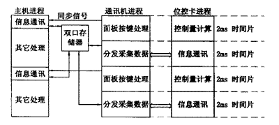
The software design work is divided into three parts: host software, communication software and location control card software. Developing a sound communication protocol is a top priority. In order to ensure reliable data transmission, the communication unit components use the time-sharing method to complete the information transmission with the host and the position control card. The synchronization relationship in time is shown in Figure 3. The division of the time slice and the synchronization relationship between the three parts are controlled by the communication machine. At the beginning of the first time slice, the communication machine sends a synchronization signal to the host and the position control card, informing the host to write new data into the dual port RAM, and at the same time causing the position control card to start position control operation. In the second time slice, the communication machine takes out the position command from the dual port RAM, distributes it to each position control card, and simultaneously collects the actual position data from each control card and writes it into the dual port RAM.

Figure 3 Relationship between processes in the CNC system
Previous page next page
The Mini duty casters series ,wheel size include 1'',1.25'',1.5'',2'',2.5'',3'' , wheel material include Transparent pu casters , white pp casters , black pp casters , red pu casters ,red PVC casters ,black rubber casters , main application furniture , little shelf , trolley carts ets .
Transparent pu casters , white pp casters , black pp casters , red pu casters ,red PVC casters ,black rubber casters
Ningbo Mywin Caster Co., Ltd. , https://www.mywin-caster.com