At this point the "C" value has been determined. In addition, we can also use the "smart animation" in the physical design to see the interference of the workpiece with the tooling when the workpiece is taken out of the slot and the minimum path is taken. One of the methods is described as follows:
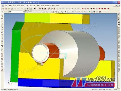
1. In Figure <5>, the measurement is marked with two dimensions, as shown in Figure <7>. The V-shaped angle is 90° and the center and right shoulder are 6.2.

Figure <7> Dimensional drawing
2. Click the “Smart Animation†toolbar, double-click to select the workpiece, click the “Smart Animation†button on the toolbar, click “Nextâ€, set the motion duration to “5†seconds, and click “Finishâ€. This step is abbreviated.
3. Click “Extension Path†on the “Smart Animation†toolbar to draw the route when the workpiece is taken out, as shown in the example in <8> in the middle of the workpiece.

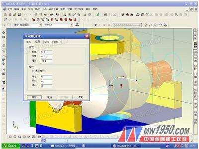
Figure <8> Editing the second point of the path
4. The mouse is close to the second point of “Route (sample line)â€. After the “Hand Shape†appears, right click on the menu and select “Key Frame Propertiesâ€. Click the “Location†menu and fill in the length of the grid with the coordinate value of 6.3 (short column Φ25/2) - Figure <7> measured size 6.2), fill the grid with the coordinate value of 6.3 (the isosceles triangle is equal to the two right angle sides), as shown in Figure <8>.

Figure <9> Edit path
5. Perform the operation described in the previous step for the third point of the “routeâ€, but fill in 20 for the length and 6.3 for the width. This step is abbreviated.
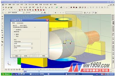
6. Left-click to select the “Route†line, right-click the menu, select “Animation Path Propertiesâ€, and select “Lineâ€, as shown in Figure <9> and <10>.

Figure <10> "Spline" path becomes "straight line"
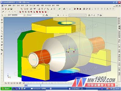
7. The picture is standing sideways, as shown in Figure <4>, click the “Play†button, then we can slowly (5 seconds) see the movement of the workpiece from the slot. Figure <4> is the state in which the animation ends. We have to play the animation from all angles to see if the workpiece and the work are equipped to interfere. At this point, the design of the tooling drawings is completed through three-dimensional transformation.
Third, the conclusion
Through the above simple example, the simulation application can be implemented not only in 3D, but also in 2D. As long as you are good at thinking, the simulation application of CAXA CAD is very promising. Engineering designers who have encountered some dimensions to be determined in the field during drawing design may be considered for confirmation in the software. Successful application can reduce the consumption of time and material resources. In today's fiercely competitive environment, whoever wins the time will be able to seize the market and the viability of the company will be stronger.
Previous page
In this section, you would find PHILIC APPROVED valve surrounding products. We can help you source them easily and provide a worry-free value-added services. Proclaim: 1) Philic doesn't produce them. 2) We have very close business relationship in these industries. 3) We will take charge of all issues occured as long as we are in business of Valve Actuators, Valve Elbow, Valve flanges, Valve Pipes, Welding Torches, Welding Machines.
Valve Actuators, Valve Elbow, Valve flanges, Valve Pipes, Welding Torches, Welding Machines.
Zhejiang Philic Fluid Control Co.,LTD , https://www.philicflow.com