Finite element analysis of complex nodes
Due to the complexity of the National Stadium, many parts of the model appear in a large number of parts. In this case, the finite element analysis of the nodes must be performed to judge the validity of the node construction. To this end, the designer specifically formulated the technical conditions for the node finite element design. The general flow of node analysis is:
Ansys/Sap2000 calculates the internal force of the component as a whole
Create a node entity model and load
Solve and observe post-processing to see if the result is satisfactory

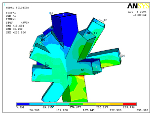
Figure 5 node Von mise stress cloud
In the finite element analysis of the solid model, the correct application of loads and boundary conditions is one of the keys to achieving reasonable results. In theory, the load applied by these partial structures is all the internal forces acting on the corresponding rods, so the axial force, bending moment, etc. on the section of the corresponding rod are added to the taken section as a load or the whole section is analyzed. The deformation produced in the case should be the most accurate way to apply constraints. In the overall model analysis, there is only a solution on both ends of each unit. The ANSYS solid model is divided into many parts by meshing, so it is faced with the problem of how to add the internal force equivalent of the overall model to the ANSYS solid model. The designers of China Academy of Architectural Design are in the solid model section. The node is established at the centroid, and the coupling function of ANSYS is used to couple the degree of freedom of the node on the section to the degree of freedom of the node of the section centroid, and then the load is added to the centroid node. This simulates the flat section assumption. For the interception length of the solid model, it is generally not more than 3 to 4 times the cross-section dimension of the member. A general principle is to conform to the Saint-Venant principle. That is, simplifying the boundary cannot have a significant impact on the outcome of the region of interest. Therefore, designers can flexibly grasp according to their needs. Figure 5 is a stress cloud diagram of a typical complex node at the top of the column.
Secondary development technology
Since ANSYS software is only a structural analysis software, it lacks the necessary support for industry specifications. To this end, the Architectural Design and Development Department of China Architecture Design and Research Institute developed the special design module of ANSYS space structure - CAG DESIGN. CAG DESIGN is primarily developed for spatial structures. In order to check the quality of the developed modules, a dedicated development team was established. The technical conditions for software development have been developed, and the standards and specifications that the procedures should follow are specified. Corresponding to the pre- and post-processing of ANSYS, CAG DESIGN is mainly divided into three parts, namely pre-processing module CAGPREP7, calculation solution module CAGSOLU and post-processing module CAGPOST. The main functions of the pre-processing module CAGPREP7 are: setting the initial environment of CAG DESIGN, the data exchange interface between ANSYS and AutoCAD, and the real constant calculation module of common cross section. According to the characteristics of the space structure, the commonly used beam elements, rod units and cable units are mainly selected. The function of the calculation solution module CAGSOLU is mainly to define single-duty load, such as constant load, snow load, wind load and temperature. These loads can be unit loads or node loads. In order to compare with other programs, the interface is reserved. In the design of the National Stadium, in order to solve the problem of loading complex, the designer first loads in the MST and then converts to the ANSYS model. CAGSOLU can calculate the seismic response of the structure according to the requirements of the project according to the Code for Seismic Design of Buildings (GB50011-2001) using the mode decomposition reaction spectrum method. The seismic response includes small earthquakes and medium earthquakes. The post-processing module CAGPOST is mainly used for the calculation of working condition combination and section. The calculated result can display the stress distribution of each rod in the form of graph on the ANSYS graphical interface. In conjunction with this, an Excel interface file was developed to adjust the model section and optimize the model.
summary
As a large-scale general finite element software, ANSYS has been widely used in the design of the National Stadium. This software has been extensively tested and the accuracy and stability of the calculations are guaranteed. Users can develop their own custom modules directly through ANSYS' open system without having to spend a lot of effort on the development platform. The Structural Technology Development Department of China Architecture Design and Research Institute is developing special modules for the space structure field for ANSYS software, providing powerful tools for architectural design.
[references]
[1] Ansys, APDL User Guide.
[2] Ansys, UIDL PROGRAMMER'S GUIDE.
[3] Fan Zhong Fan Xuewei Liu Xianming Liu Yan The application of the thin-walled box-shaped members in the large-span structure of the National Stadium. Proceedings of the 4th Modern Structural Engineering Symposium. July 2004, Ningbo, Zhejiang.
Previous page
Bamboo Wood Board Horse Stable Panel,Bamboo Wood Cutting Board,Bamboo Charcoal Wood Mirror Board,Nano Bamboo And Wood Fiber Wall Board
Linyi Hmbyan International Trading Co.,Ltd , https://www.hmbyandecor.com