AC motors are multi-variable, non-linear and strongly coupled systems. Realizing the high-performance control of AC motors is an important part of current AC drive research. There are many control methods in this area, such as field-oriented control, partial state feedback, precise input/output linearization decoupling control, adaptive input/output linearization decoupling control, passive methods, and backstepping control. All of these methods need to know in advance part or all of the state of the system, especially the uncertainty of the load will affect the control effect.
The backstepping control method is applied to a control system of a non-linear induction motor, and the load is taken as an uncertain parameter to introduce an adaptive mechanism. Through state observation, the speed and flux linkage can be well tracked, and the control structure of the system is simple. Simulation results demonstrate the effectiveness of the method.
2 Induction Motor Adaptive Pushback Control 2.1 Mathematical Model of Induction Motor Under the assumption of equal mutual inductance and linear magnetic circuit, the induction motor is in the synchronous rotating coordinate system (d, q), and the rotor flux linkage is in the direction of d axis. (ie field-oriented control), its mathematical model is as follows: Shanren, professor, doctoral tutor, engaged in complex system control, power system control and other research.
In the formula, resistance, self-inductance, mutual inductance, current, flux linkage, rotor angular velocity and voltage subscripts s and r are the stator and the rotor (d, q) are the two phases synchronous rotation coordinate component n is the pole pair number J is rotation The inertia T is the load torque.
The goal of control is to speed track the desired reference speed, and the flux amplitude tracks the desired reference flux linkage. The reference speed represents the desired mechanical output performance, and the reference flux chain represents a measure of improved efficiency.
2. 2 Adaptive Backstepping Control Design In order to realize the goal of speed and magnetic flux amplitude tracking, the adaptive backstepping design steps are as follows: Step 1 For tracking the target of speed and flux amplitude, define the tracking error as the error. Derivatives are treated as i and are controlled. When the parameter T is known, the Lyapunov function V] is used. In order to obtain stable feedback, the condition e is assumed to be k (3). Given that the parameter T is known, In order to meet the speed and flux chain amplitude tracking requirements, the state variables are expected to perform. When T is unknown, then using its estimate T (3) becomes as follows. Equation (2) can be expressed as where T is the estimation error. The dynamic equation of e is the third step in the formula. In order to obtain the update rule of the control and parameters, add the sum T to V to form a new Lyapunov function, ie k is a positive number. From the equations (5) and (6), the control and decision equations can be obtained. k 0. If the following control laws and parameter adjustment rules are taken, then V, (8) is the adaptive backstepping control law for AC motors. It is based on the magnetic field orientation, taking into account the actual load of the AC motor when the actual load is obtained, to overcome the lack of load changes in the original magnetic field orientation control, compared to the adaptive input and output linear decoupling control, The structure is simple and easy to implement.
3 System Simulation The block diagram of the AC motor adaptive backstepping control system is shown in Figure 1. In order to verify the effectiveness of the control, simulations were performed using MAT LA B5.3 SIMU LINK. The motor parameters used for the simulation were: R speed 182 rad/s, rated load 12 Nm, rated rotor magnetic induction motor adaptive backstepping control system The simulation parameters taken as k become 0. 25 Wb at t = 1. 5 s, and the tracking process is shown in Figure 3. Figure 4 shows the actual value of load torque (12 Nm) and its estimated value.
4 Conclusions From the simulation results, we can see that the new adaptive backstepping control method can realize the nonlinear control of induction motor. Whether the load is determined or not, the speed of the motor and the rotor flux can be well tracked through state observations. The control structure of the system is simple. The simulation results show the effectiveness of the method. This method is easy to implement.
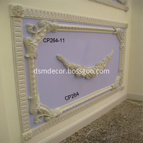
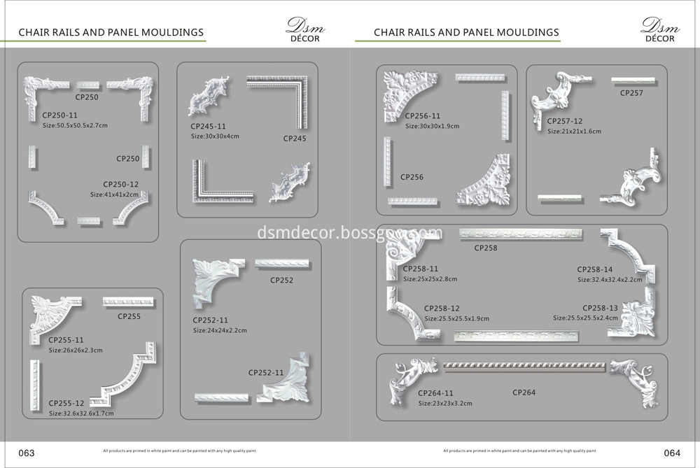
Polyurethane Panel Molding Corners CP264-11 matchs Panel Molding CP264.

Decorative Panel Moulding PP332 matchs Polyurethane Corners PP332-16.

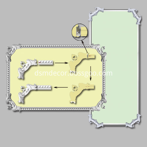
Various Hand Carved Polyurethane Corner, Luxury Polyurethane Corner,Polyurethane Pu Corner, Polyurethane Ceiling Corner, Cornice Corners, Crown Corners , Inside Corner Molding are avaliable, some Polyurethane Corners are special designed for special mouldings, easy to install, combine mouldings with Polyurethane Corners, you may creat beautiful picture frame.
Muti-functional style Polyurethane Corners are enable plain or Carved Panel Mouldings jointing perfectly, can enhance the effect of decration.
You may choose plain or flower Polyurethane Corners to match the Panel Molding, achieve perfect design.
Advantages of Chair Rails and Panel Moldings :
1. Elegant European style
2. Many models to choose from
3. Suitable for both DIY and construction projects
4. Superior to Gypsum moldings
5. Light weight, easy to transport and install
6. Elaborate patterns
7. Beautiful Matching
8. Labor efficient

Polyurethane Corners
Polyurethane Corners,Hand Carved Polyurethane Corners,Luxury Polyurethane Corners,Polyurethane Ceiling Corners,Chair Rails and Plain Panel Mouldings
Suntronic New Materials Technology Co., Ltd. , https://www.dsmdecor.com