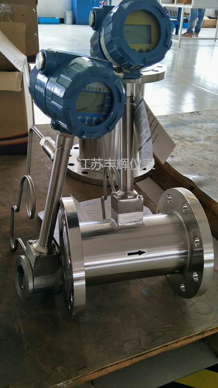
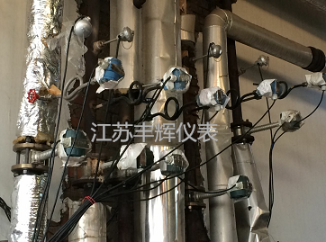
First, classification:
Split type: (composed of flow sensor, flow totalizer) is suitable for occasions where the installation location is inconvenient to view data. It is composed of a flow meter, a flow totalizer or a paperless recorder, and can be combined with a temperature or pressure sensor to form a separate type of temperature and pressure compensation type: Field display value. The corresponding output or interface or protocol can be configured to transmit signals over long distances and be networked with computers. The integrated vortex flowmeter can choose to increase temperature compensation or pressure compensation or both at the same time when measuring gas or steam.
Insert type: DN200----DN2000 large-diameter pipe, convenient for transportation, installation and cost-saving. The plug-in type can be formed by the above two (split, integral) type conversion vortex sensor mounting methods.
Reduced diameter type: It can be used to measure fluid flow in pipes with large pipe diameter or small flow rate. (Reduced diameter can be directly on the pipeline, as inconvenient on-site changes can also be performed on the body)
Steam-specific: A steam metering flowmeter developed and improved for steam medium characteristics.
LUGB-80 vortex flowmeter specification
Second, technical indicators:
1. Measurement medium: liquid, general gas, natural gas, steam (saturated steam and superheated steam);
2, the possible range of measurement: Reynolds number of 5 × 10³ ~ 7 × 10⁶
3, the normal measurement range: Reynolds number of 2 × 10⁴ ~ 7 × 10⁶
4, measuring the flow rate range: liquid 0.5 ~ 7m / s gas 4 ~ 35mm / s steam 7 ~ 70m / s
5, measured fluid temperature: -40 °C ~ +350 °C
6, measured fluid pressure: 1.6,4,25MPa
7. Accuracy: Level 1, Level 1.5, Level 0.5 (up to 0.5 through non-linear trimming);
8. Repeatability: 0.2% of the indicated value;
9, table body material: ICr18Ni9Ti;
10, pressure loss: △ = 1.2 × r × V2 × 10-6 where: △ P - pressure loss r - fluid density measured (Kg/m3) v - average tube velocity (m / s)
11, the ambient temperature: -20 °C ~ +55 °C (special requirements order description)
12. Ambient humidity: ≤ 90% RH
13, atmospheric pressure: 86-106KPa
14, external power supply: 3.6 ~ 224VDC
15, internal power supply: 3 ~ 4.5VVDDC
16, working power: 80/A
17, working voltage: 2.7 ~ 3.6v
18, operating frequency: 0.1 ~ 3000H
19, signal output: pulse output (external power supply) current output 4 ~ 20mADC (two-wire supply for 24VDC power supply) pulse output and current output can only choose one way.
LUGB-80 vortex flowmeter specification
Third, install:
Vortex flowmeters provide sufficient straight sections upstream and downstream to ensure a non-curved symmetrical profile. Install the valve downstream of the instrument whenever possible.
Vertical installation is usually the preferred choice. The upward-moving fluid ensures that the instrument is always full and the components in the medium are evenly distributed.
When installing in long pipelines that are prone to vibration, removers should be installed upstream and downstream of the flowmeter.
For gas applications, installation of the instrument should be avoided at the bottom of the U-bend to avoid the phenomenon of water hammer caused by the absorption of condensation and driving. The strength of the water hammer causes the sensor to overstress, resulting in permanent damage to the sensor.
Faced with so many varieties of gas flow meters, the selection of general users has become a problem. How to scientifically and objectively select a flow meter is a problem that needs attention. We believe that the type selection should follow appropriate rules, try to avoid misleading propaganda from vendors, and find a right flow meter for itself. It is its ideal flow meter.
Wide measuring range, general range of up to 1:15 or more. Saturated steam flow meter, low pressure loss, low energy loss, easy to meet the following range of energy flow rate range, the lower limit can be extended to 2/3.
Fault phenomenon
Possible causes and treatment methods
After the power is turned on, the flowmeter has no zero (4mA) output.
The positive and negative poles of the power cord are reversed. Should be reconnected.
The power supply voltage is wrong. Check the voltage on the flowmeter terminal should be in the (17 ~ 30) V range.
Secondary table lead line failure. Check the line.
When there is flow, the flow meter has no output current.
Pipeline flow is less than the lower flow rate that the flowmeter can detect. Change the pipe diameter and increase the flow rate.
The gain of the amplifier board is insufficient or the trigger sensitivity is too low, adjustable K1 or K2.
Poor contact between the amplifying plate and the coefficient plate. Clean the connection points, reload the coefficient plate, and tighten the stud nut.
Instrument circuit failure, find out the faulty part of the circuit for repair.
There is no flow in the pipe, but the flowmeter has a signal output.
Zero bias. Zero (4mA).
The pipe vibration is intense, causing the instrument to have an output signal. Reinforce pipes and reduce vibration.
Trigger sensitivity is too high. Adjustable K2, so that the TP3 output just disappears, the pointer on the scene pointer back to 0%.
Instrument circuit failure, find out the faulty part of the circuit for repair.
Flowmeter output signal is not stable, the pointer swings too much.
Process flow is at the critical point of the meter's lower flow point. Adjustable K2 and damper switch for stable output.
Poor contact of the circuit or leads, check contact points.
When the flow rate increases, the output current does not go up.
The load resistance of the flowmeter is too large. Reduce the load, or increase the power supply voltage, up to 30V.
circuit failure. According to Section 7 method inspection.
The flow shows a large deviation.
The flow meter setting range (Qmax) and the secondary instrument set range are not correct. Re-adjust the secondary meter range.
Flowmeter transformation factor KB calculation error. Recalculate KB and select J.
The design conditions are different from the actual conditions. Recalculate KB and J coefficients according to actual conditions and readjust them.
The wrong position of the KB encoder switch or the incorrect position of the J connector. Re-adjust the switch, connector.
Circuit failure, maintenance.
Â
Led Bathroom Light
Shower Light Fixture,Modern Bathroom Lighting,Led Shower Light,Bathroom Ceiling Light
NINGBO EASTKEY ILLUMINATE APPLIANCE CO.,LTD , https://www.dkledmirrorlight.com

