The cylinder is an important part of the automobile engine. It connects the machine with many parts of the components and the exhaust pipes in a single unit, keeping them in the correct position and moving in coordination with each other. Since the cylinder block is a complex structural component that is precisely cast, its dimensional accuracy and positional accuracy are required to be high. In order to ensure the machining accuracy of the cylinder workpiece, the machining is very difficult. The use of ordinary machine tools produces poor precision and low efficiency, and some parts are controlled by the operator's level and are also affected by machining errors. Based on the above problems, the user has put forward the requirements for fully automatic processing of cylinder parts in mass production.
The VMC2180s vertical machining center produced by our company is mainly used for processing parts such as plate parts, disc parts, housing parts and molds with high precision, many processes and complicated shapes. It can continuously finish milling and drilling in one setup. Expansion, hinge, boring, tapping and precise machining of two-dimensional, three-dimensional curved surfaces and bevels, processing is realized, the production cycle is shortened, and one machining center replaces three ordinary machine tools to machine the body parts, thereby enabling users Get good economic results.
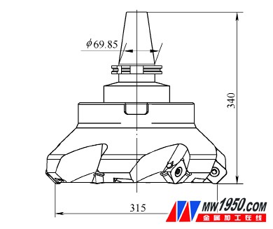
In order to meet the automatic machining requirements of the engine block and improve the production efficiency, only the automatic machining of the machine tool can not meet the requirements of the user, which means that the clamp must also be designed to be positioned and clamped to achieve full automatic. Some users have one of the parts processing requirements for the top surface machining, and the top surface size of the machine body is 1062mm × 260mm (see Figure 1), which means that the diameter of the face milling cutter for machining this surface must be ≥ 260mm. In the actual machining, a φ315mm face milling cutter with a wiper was selected (see Figure 2). Such a large-scale tool exceeds the tool loading and tool change conditions of the VMC2180s machining center regardless of the tool size or tool weight. The VMC2180s machining center has a magazine capacity of 32, the tool length is 400mm, the maximum cutter diameter is 125mm, the adjacent vacancy is 250mm, and the tool quality is up to 20kg. The tool has a diameter of 315mm, a length of 340mm and a mass of 31.6kg on the top surface of the machine body. It exceeds the automatic tool change condition of the machine tool. This tool cannot realize automatic tool change on the machine tool changer. In order to meet the processing needs of users, the following solutions are provided.

Figure 1 Schematic diagram of the cylinder block

Figure 2 face milling cutter
Overall program
The working table size of the VMC2180s machining center is 2000mm×800mm. Then, a milling cutter holder for machining the top surface of the cylinder is placed on the left side of the table, and a fully automatic positioning clamping fixture is placed on the right side (see Figure 3).

Figure 3 Tool holder, fixture diagram
1. Tool holder 2. Cylinder block 3. Workbench Fixture design
The fixture is positioned by two holes on the bottom surface and the bottom surface of the engine block (ie, the typical positioning mode of one pin and two pins), pressing the two sides of the cylinder body, finishing the top surface, processing the holes on the top surface, and finely drilling the hole of the cylinder.

Figure 4 Automatic hydraulic clamp three views
1, 4. Pre-position 2. Support plate 3. Non-contact switch 5, 7. Guide support 6. Thrust cylinder Firstly, the cylinder parts are placed on the support plate on the clamp body along the guide support (see Fig. 4), and the workpiece is accurately positioned for rapid and unmanned intervention, and the workpiece is reliably clamped, and the pre-positioning device is added to the fixture design. Then press the start clamp clamping button, then the thrust hydraulic cylinder pushes the cylinder block part through the piston rod and the pressure plate connected thereto, and the cylinder part will approach the non-contact switch, and the non-contact switch will give The machine system feedback signal, the machine system commands, and the thrust cylinder retracts to its original position. The hydraulic cylinders all select the induction hydraulic cylinder. When the piston moves into position, it will feed back the signal to the machine system. The machine system will issue a command again and then the hydraulic cylinder will receive the start command to push the positioning pin into the cylinder part positioning hole. In the same way, the clamping hydraulic cylinder starts to drive the pressure plate to clamp the body parts, and the positioning and clamping of the entire cylinder parts without intervention is completed.
Tool change for large size milling cutter
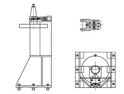
First, fix the knife holder (see Figure 5) on the left side of the workbench, then install the check rod for the alignment on the tool holder, and then install the probe on the machine spindle to find the center position of the inspection rod. The value is written in the machine coordinate system to determine the position of the tool change point. Then the tool is programmed in the machining program like other tools. When machining the top surface of the cylinder part, the spindle will be taken from the tool holder according to the programmed machining program. Take the milling cutter for the top surface of the machine body and realize the automatic tool change of the large-size milling cutter from the surface.

Figure 5 Three views of the tool holder
Conclusion
The whole cylinder processing process adopts the VMC2180s vertical machining center, the fixture is a fully automatic hydraulic clamp, and the milling cutter that unconditionally completes the automatic tool change in the tool magazine is placed on the tool holder, thus realizing the automatic tool change of all the tools. . In all processing, no manual intervention is required, the positioning of the workpiece is reliable, and the clamping process is safe, simple and fast, which greatly improves the processing efficiency and realizes highly informationized and automated processing.
Other Door Accessories
Sectional Door Accessories: motor 220V-380V, control box, spring break device, cable break device , aluminum alloy rope pulley, enhanced shaft bracket, air bag system, duplex enhanced guide wheel bracket.
Detail introduction for above main accessories
1.Motor and controller:
The garage door operator is designed for residential overhead sectional and tilt doors.
The operator memorizes the limit positions and unique braking system that slows the unit down at the end of its travel.
Rolling code remote control with max. 20 pcs hand transmitters.
The operator is equipped with a manual release lever which allows manual operation of the door in case of power failure.
The controller has a security LOCK function which prevents operation of the door from transmitter.
2.spring break device:
Sectional doors are hinged and they bend in the tracks as the door opens and closes. Many of these doors are counterbalanced with extension springs, also designated "stretch springs," and they have seven characteristics. The length is the measurement of all the coils pressed together. This, along with the inside diameter of the coils and wire size - the thickness of the wire from which the springs are made - determine the stretch, the distance the spring is extended - normally half the door height, and pull, the force the spring pulls when stretched its normal length. The type of ends determine how the ends of the spring are mounted. The initial tension is the percentage of pull needed to separate the coils. This is determined by the pitch with which the springs are wound. On sectional garage door springs this is normally 15 percent. For example a 100 pound pull spring requires 15 pounds of weight to separate the coils; when a door is open the two springs will support 15 pounds of door weight without any stretch.
Most extension springs are made of oil tempered wire. These are normally coated or painted. Some springs are made of galvanized wire.
3.able break device:
cable break device ,door hardware
adjustable bottom bracket .
the raw material hot plate
zinc plated
safety device
adjustable bottom bracket
the raw material hot plate
zinc plating
spring safety device ,2" and 3" safety device
once the cable is broken ,this devoice can keep the hurt away from the door falling
4.aluminum alloy rope pulley
Equipment: CNC stamping/punching machine, CNC bending machine, CNC cutting
machine, 5~250 tons punching machines, welding machine, polish machines...
Processed material: stainless steel: copper, carbon steel
Surface treatment: Hot galvanized, polishing
Making process:Stamping, deep drawing,bending, punching, laser cutting,threading,
welding, tapping, riveting, grinding
5.air bag system
It is a safety device. When the door is down to hit something, it will up automatically.
Operation pressure:<3mbar
Battery:CR2032*2
Battery lifetime>1 year
Emission frequency: 315MHZ
Emission power:<10mW
Receiver power source:12V
6.duplex enhanced guide wheel bracket
Determining the right type of sectional door roller for your garage door tracks can be a little confusing, especially when you do not know what you need to look for in a garage door roller. To simplify things, there are two primary things you need to be aware of. First are the actual dimensions of the roller, and second is purpose that you will be using the door for. You can read below about measuring your roller and choosing the right quality of material for your door.
Other Door Accessories,Electronic Door Accessories,Automatic Door Accessories,High Speed Door Radar Detector
Shenzhen Hongfa Automatic Door Co., Ltd. , https://www.hffreezerdoor.com


