When CNC milling deeper cavity parts, because the rod milling cutter clamping method belongs to the cantilever structure, the farther the tool side teeth are from the tool holder during machining, the worse the milling rigidity is, which causes the cutting to make the tool amount inconsistent, and the inner cavity side is caused by milling. The wall size is small and large, commonly known as "inverted trapezoid". If the dimensional accuracy requirements are low, the depth direction can be solved with layered milling, but there are joint marks between the layers. If the precision size of 7 or above is processed, the milling of the bar milling cutter will be difficult to ensure the accuracy and the surface roughness of the side wall will be poor.
In order to solve the practical problems in the machining center milling, the author uses the machining method of boring tool instead of milling cutter layer by layer scanning, which solves the problem of machining the side wall of the cavity and ensures the surface roughness of the sidewall is 0.8μm. In the processing of a number of research institutes, it plays a key role in ensuring the precise size of the shaped cavity. The economic benefits directly generated by this process improvement exceeds one million yuan. Because of the leading processing technology, the accuracy of the shape and position of the key parts is guaranteed. The amount of processing contracts signed by the returning customers is steadily increasing, and the pricing power of the heavy parts is mostly in our side.
1. Development status and trends
With the popularization of electric spindle high-speed CNC machine tools, the extensive use of coated tools such as titanium and ceramic tools makes our processing range wider, and the tool rotation speed can achieve quasi-high speed machining of 8000~12000r/min, 15000~50000r/min. High-speed machining, with the processing method of layer-by-layer scanning, the processing time will be greatly reduced, and the processing of key components will play a greater role. This processing concept will be widely used.
2. Creative design content
The idea originated from the fact that when our department undertook the processing of large shell parts of a research institute, the precise size of the parts appeared in the same round hole with the flat hole and the common cylindrical surface structure. At first, it was not taken seriously. When the machining center was actually milling, the hole and the bottom of the hole were found. The dimensions after processing are inconsistent, commonly known as "horn", and the secondary milling of round holes and flat holes produces serious seam marks. When the flat holes are milled, round holes are formed, forming a four-section arc, which cannot guarantee the dimensional accuracy of the shape.
After analysis, the main reason is that the rod milling cutter is a cantilever structure. The farther the tool side teeth are from the tool holder, the worse the milling rigidity is. If the milling is performed, the side teeth close to the tool holder will be secondly milled to the front side teeth. The side walls of the cavity have been milled, resulting in inconsistent amounts of the knife, forming an "inverted trapezoid" or "flare" phenomenon. It is necessary to eliminate the problem of inconsistent knives and the problem of the side wall of the secondary milling. The boring is inspired by the small amount of the knives, and the innovation is changed. The machining method of using the boring tool instead of the milling cutter layer by layer scanning is adopted.
Common understanding: when the milling cutter is used to mill the cavity, it is formed by milling the side teeth according to the programmed path. The deeper inner cavity is layered milling. The layering depth is generally set to 1~5mm, which is suitable for lower precision cavity machining. After rough milling, I use the boring tool to press the programmed trajectory to the inner cavity contour. The inner cavity depth is layered and each layer is set to t=2[h(2r-h)] 1/2 (see Figure 1 for the calculation method). , to ensure the processing roughness ≤ 0.8μm, layer by layer scanning to form the inner cavity sidewall. Due to the micro-rotation boring, the cutting force of each layer is nearly equal, and the cavity machining solves the problem of the knives, and the sidewall roughness value R a ≤ 0.8 μm.
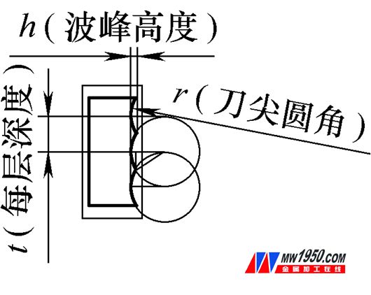
Figure 1 Internal cavity depth stratification é•— residual peak
Let: the depth of each layer is t, known: the radius of the file is r, h ≤ roughness R a .
(t/2) 2 =r 2 -(rh) 2 =2h(rh)t=2[h(2r-h)] 1/2
(1) Technical principle and theory According to the cutting trajectory of the conventional boring of the machining center, the dense spiral forms the side wall of the hole.
When the bar milling cutter is used to mill the side of the cavity, the side of the milling cutter is used as the busbar to form the sidewall of the dense busbar according to the programming track; the milling hole and the arc track adopt the differential arc interpolation principle, so that the dense busbar forms the column hole or the curved surface. Side wall.
Take a typical part (see Figure 2) as an example. If you are machining a fixed-axis, fixed-steering aluminum alloy part, the accuracy is 7 steps, the upper part is a round hole, and the lower part is a flat hole of the same diameter (total depth 50mm or so), roughness 0.8μm, the processing problem appears, the pupil is required, the lower part is the flat hole can not be smashed; the hole is to be milled, the machining precision is poor, the roughness is poor, the side wall allows the knife, the upper hole and the lower arc secondary machining will produce the knife mark.
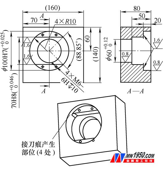
Figure 2 Schematic diagram of a typical part
The main difficulty in the machining of parts is that the side wall allows the knife to have a knife mark; the surface roughness is poor. Milling holes is not feasible, and it is only possible to find a solution in the pupil. It is impossible to open a flat hole. This is to break the traditional thinking concept and innovate and change. We self-programming, programming and operator trial processing, testing and correcting processing parameters, using the first unilateral retention 0.06mm rough machining cavity shape, and then using Φ20mm double-edged symmetrical boring tool, according to the programmed trajectory cyclone interpolation fine upper part The circular hole and the two circular arcs with the same diameter of the lower flat hole of the fine boring are changed from the dense spiral cutting path of the conventional boring to the cutting trajectory of the dense equal-diameter concentric circle, and the scanning trajectory is not carried out by the programmed trajectory.镗The upper round hole and the lower circular surface of the fine boring. Because the high-speed micro-switch does not change the cutter continuously, the cutting force remains the same, the boring tool is the cutting edge, the rigidity of the boring bar at the tool tip is constant, and the problem of the knives and the knives is solved in the process to ensure the sidewall roughness value. R a ≤ 0.8 μm.
(2) Ways to achieve and feasibility analysis
   The machining path has been determined, and the specific implementation depends on calculation.
Using SolidWorks 3D software to draw the residual peak map of the cavity contour cutting path, it is required to achieve the roughness value Ra=0.8μm specified in the pattern (see Figure 2).
Use CK basic tool holder, code TW2026E, (parameters are from Dazhao Seiki Co., Ltd., BIG+KAISERCK modular file series). According to the corner size of the figure 2 × R10mm, a double-edged symmetrical boring tool is selected, and the diameter of the boring tool is plotted as φ20 mm, and the peak value of the circumferential cutting residue is calculated (see Fig. 3).
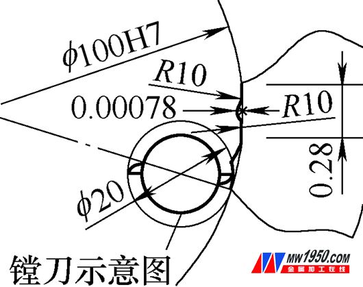
Figure 3 Cavity contour cutting trajectory residual peak magnified view
Calculate the cutting parameters according to the arc cutting residual peak map: when the feed per tooth is ≤0.28mm/r, the roughness can be satisfied 0.8μm÷1000=0.0008mm, the feed per tooth=0.28mm/r, cutting residue Peak = 0.00078 mm < 0.0008 mm.
Set: Tool speed F=6000r/min, then: circular path feed speed S=6000r/min×0.28mm/r=1680mm/min (with tracking track radius tool compensation), φ100mm hole circumference=100mm×3.14= 314mm/week, the number of revolutions per week of the tool = hole circumference 进 feed per tooth = 314mm / circumference ÷ 0.28mm / r ≈ 1121r / week, hole weekly cutting time = weekly rotation number ÷ tool speed = 1111 ÷ 6000 ≈0.1868r/week × 60≈11s.
The total length of the two arcs = 100 × (88.85 ° ÷ 180) × 3.14 ≈ 154.99 mm, the total number of revolutions per week = the total length of the two arcs 进 the feed per tooth = 154.99 ÷ 0.28 ≈ 553.54r / week, each arc Week total cutting time = total weekly revolutions of the arc ÷ tool speed = 553.54r / week ÷ 6000r / min ≈ 0.0923min / week × 60 ≈ 5.5s.
Using SolidWorks 3D software to draw the residual peak map of the cutting path of the cavity depth scan, the roughness value Ra≤0.8μm (see Figure 4) is required.
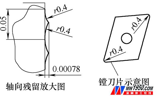
Figure 4: The inner cavity of the knife is scanned by layer by layer.
Using the machine clamp type 代 blade (code CCGP060204FLA), the file edge fillet r=0.4mm, (parameters are from the Dazhao Seiki Co., Ltd., BIG+KAISERCK modular file series).
Set the cutting parameters according to the residual peak value of the depth of the knife:
When the axial depth of each layer is ≤0.05mm/layer; the roughness is 0.8μm÷1000=0.0008mm, the depth of each layer is 0.05mm/layer, the peak of cutting residue=0.00078mm<0.0008mm, the known hole depth =20mm, hole cutting time per week = 0.1868min / week, knife depth per layer = 0.05mm / layer, circular path interpolation pupil time = 0.187 × 20 ÷ 0.05 = 74.8min; known two arc depth =50-20=30mm, total arc cutting time per week = 0.0923min/week, circular path interpolation 镗 two arc surface time = 0.0923×30÷0.05=55.38min; total processing time=74.8+55.38=130.18min .
The processing method is mainly applied to CNC machine tools with higher rotation speed (speed greater than 8000r/min). The residual peak map of cutting path is calculated by SolidWorks 3D software. Under the conditions allowed by the machine tool and tool, the tool speed is increased as much as possible, and the track is increased. Give speed and increase production efficiency.
3. Innovation
When our department undertook the processing of large-shell parts of a research institute, the processing method of layer-by-layer scanning with a boring tool was used for the first time. The high-quality completion of the aviation product processing task was praised by Party A. This processing technology innovation breaks the traditional concept that the boring tool can only process round holes. On the basis of high-speed cutting, after rough milling in the inner cavity, the boring tool can process both flat holes and various types of cavities. It solves the phenomenon of “inverted trapezoid†or “bell†caused by milling.
4. Application and promotion
(1) It is actually applied to the processing of large shell parts of a research institute (the origin of ideas), as shown in Figure 5:
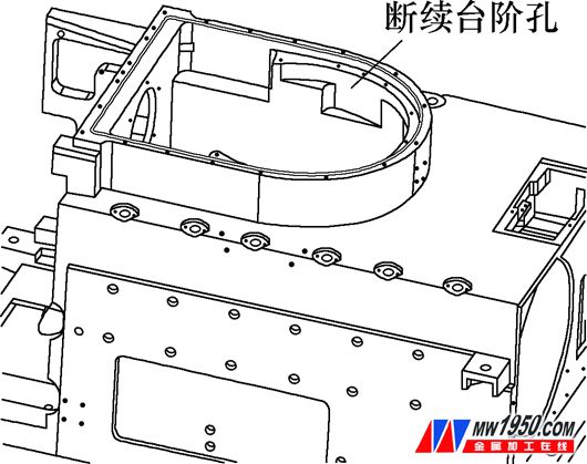
Figure 5 applies layer-by-layer machining with a boring tool
After rough milling the inner shape, the boring tool fills the round hole and the broken step hole according to the programming trajectory difference, which solves the problem that the knife "horn" phenomenon and the joint between the step hole and the round hole are solved.
(2) It is applied to the processing of “U-frame†parts of a research institute, as shown in Figure 6:
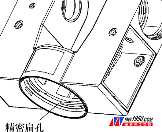
Figure 6 is applied by the layer-by-layer scanning method of boring tool
(3) The idea is extended to the processing of parts of a foreign factory, as shown in Figure 7 and Figure 8:
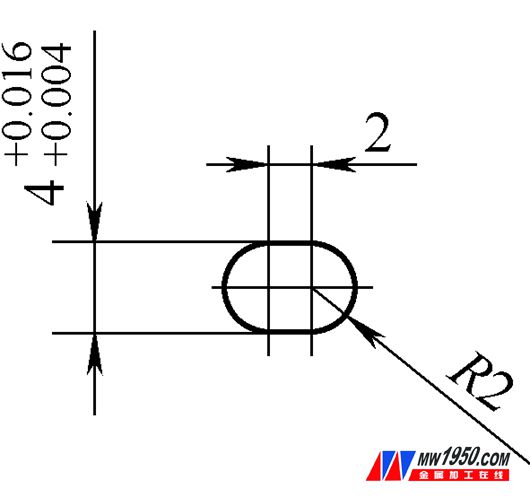
Figure 7: Precision groove enlargement
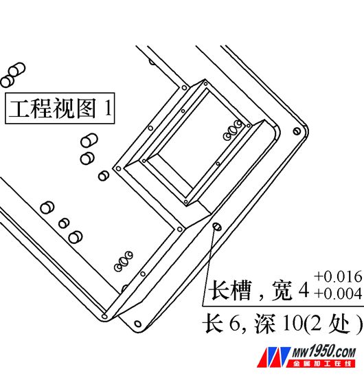
Figure 8 parts drawing
Processing 7-level precision long groove, width 4G7, length 6mm, depth 10mm. Milling produces a knife, an electrical pulse produces an electrode loss to form a tapered groove, and a wire cut cannot process a blind groove. I use a dense row of boring holes and a lamination method to make long grooves. It is known that R=2mm and h≤0.0008mm.
t=2[h(2r-h)] 1/2 =0.113mm
Number of pupils in the slot length direction = R center distance at both ends ÷t=2÷0.113≈18 times
(4) The flexible application of the formula t=2[h(2r-h)] 1/2 : when milling the inner and outer straight contours,
If the pattern requires a side roughness of 3.2 μm, the cutter diameter φ10=2r, then t=0.358mm; if the tool speed=1000r/min, the tool maximum feed amount=1000×0.358=358mm/min.
If the pattern requires the side roughness value Ra=1.6μm, the cutter diameter φ10=2r, then t=0.253mm, if the tool rotation speed=1000r/min, the maximum tool feed amount=1000×0.253=253mm/min.
Applying the formula in turn can be used as the basis for the maximum feed rate of the selected tool, minimizing the processing time and improving production efficiency.
5. Economic and social benefits
When our department undertook the processing of large-shell parts of a research institute, the processing method of layer-by-layer scanning with a boring tool was used for the first time. The processing task was completed with high quality and won the praise of Party A. The processing cost of the first batch of parts was 60,000. Diversified, a total of 4 pieces (see Figure 5); due to the quality assurance, signed and processed 3 batches of similar parts, a total of 12 pieces.
It is widely used in the processing of “U-frame†parts of a research institute. The first batch of parts processing costs more than 40,000 yuan, and a total of 3 pieces are processed (see Figure 6). As the quality is guaranteed, three batches of similar parts are signed and processed. In total, there are 7 pieces, including the processing and trial production of the complete set of “tracking device†products of the batches of the institute. The cumulative output value of the entire batch of products is about 1.7 million yuan.
The idea is extended to the processing of parts of a foreign factory. The first batch of parts processing costs more than 4,000 yuan, a total of 11 pieces of processing (see Figure 8); due to quality assurance, signed and processed the second batch.
The manufacturing department where the author is located is a precision manufacturing workshop. Most of the external products produced are important parts of the institutes. The quality problems of any one part not only increase the production cost of the workshop, but also affect the company's image and compliance rate. The company has won a good reputation for its high quality by ensuring the high quality of its products.
stainless steel, sink strainer,fruit vegetable washing drain basket,kitchen tool,draining rack, draining basket.
Shenzhen Lanejoy Technology Co.,LTD , https://www.grill-mesh.com